- Messages
- 145
- Points
- 28
- Thread starter
- #21
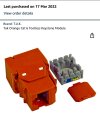
Sorry but it's me again, with the same old problem but just to recap, I have a Hikvision DS-2DE4220IW-D 2MP external IR PTZ (12V) PTZ camera on my system and it started to drop out. I kept getting the "NO LINK" message on my screen and after fiddling around with a connector on the ethernet cable in our miniscule loft I got the camera back again. At this stage I was convinced that it was a cable connection that was causing the breakdown in data transfer.
The camera ran for about a week and then suddenly dropped out again. I couldn't get it to work when I tried fiddling with the two RJ45 cable ends that are in the connector (image in #1). I checked the transformer output lead and I have 12V going to the camera.
And so I bought a circuit tester and tested the data cable from the connector in the loft back to the NVR and that was O.K. So then I bought a crimp kit with push-through RJ45 connectors and after a bit of practice on a spare cable I replaced the RJ45 connector on the loft-end of the cable that runs from the connector in the loft out to the camera. But I still had no camera after I had done that. I 'phoned the suppliers and asked if someone could come and fix it for me and they just were not interested ! "We don't do maintenance" !!!
And so I have a couple more questions if I may please. Is it an RJ45 plug on the end of the cable where it goes into the camera ? I searched on-line and even though I found a manual for the camera there were no images of what I am likely to find inside it if I do decide to investigate. I have attached an image of the camera taken from ground level and I can see what looks like an inspection cover on the underside of the camera arm. Is access possible at that point and if so can I detach the cover and find and detach the ethernet cable so that I could run a test between that end and the end that goes into the NVR i.e. the full extent of the cable ?
Thanks in advance for any help anyone can give.